
BIM Modelling, Plumbing Coordination & Sleeve Placement
PROJECT OVERVIEW
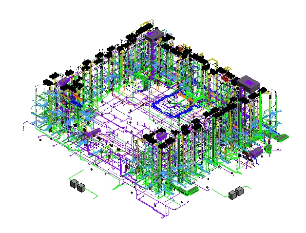
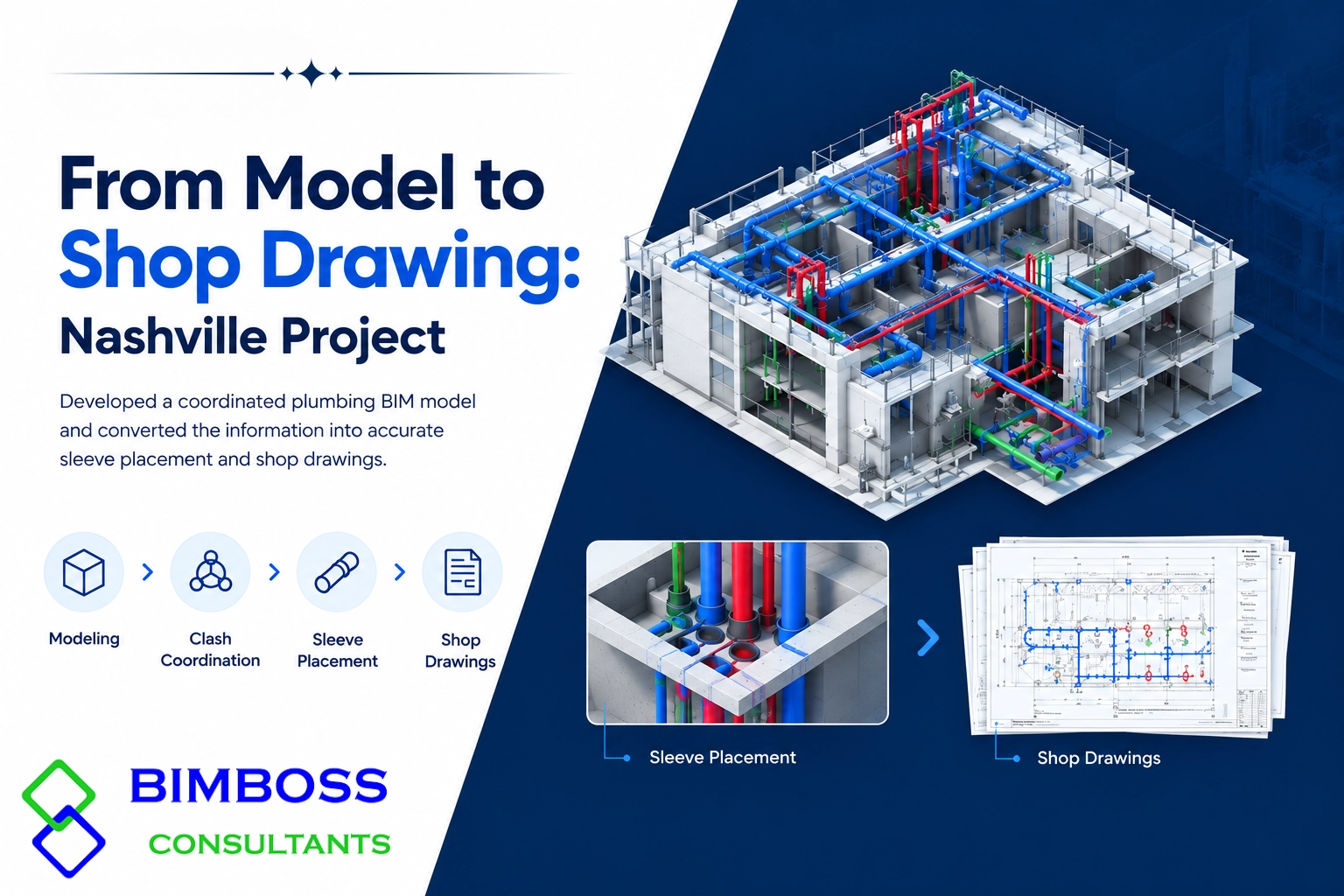
The Nashville Project focused on developing a coordinated plumbing BIM model and converting the coordinated information into accurate sleeve placement and shop drawings.
The workflow connected modelling, clash coordination, sleeve placement, and documentation into one integrated BIM process.
PROJECT CHALLENGE
Plumbing systems often pass through highly congested building areas where they must interface with structural elements, architectural components, and other MEP services.
For the Nashville Project, the key requirement was to develop coordinated plumbing information that could support accurate penetration planning and reliable shop drawing production.
The challenge was not limited to creating the plumbing model. The workflow needed to connect modelling, coordination, sleeve placement, and drawing production so that changes could be carried consistently through the project.
SCOPE OF WORK
Coordinated BIM Modeling & Documentation:
- Plumbing BIM modelling in Autodesk Revit
- Development and coordination of plumbing service routes
- Pipe routing and elevation coordination
- Identification and resolution of spatial conflicts
- Coordination with architectural and structural elements
- Sleeve placement based on coordinated pipework
- Clash detection and coordination using Autodesk Navisworks
- Preparation of plumbing and sleeve shop drawings
- Model-to-drawing QA/QC
- Final coordinated documentation for project delivery
END-TO-END BIM WORKFLOW
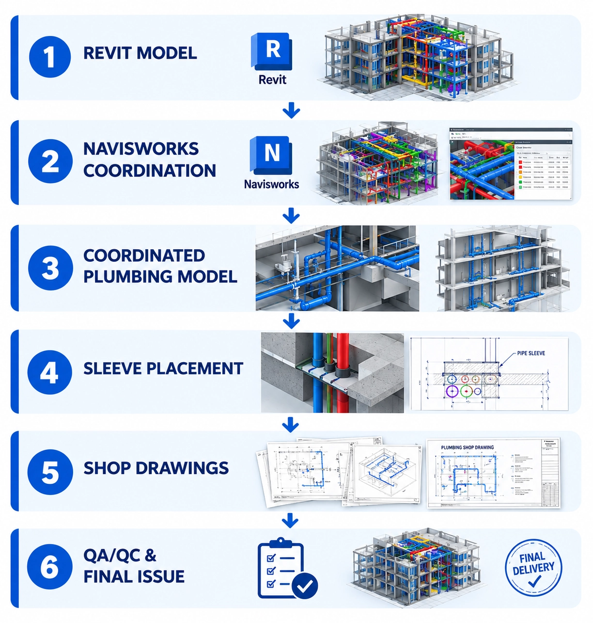
The project followed a connected workflow rather than treating modelling and documentation as separate activities.
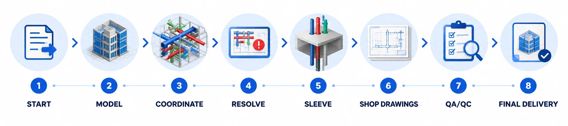
01. Project Information Review
Available architectural and structural information was reviewed, including levels, grids, openings, building elements, and coordination data.
02. Plumbing BIM Modelling
Plumbing systems, pipe routes, connections, elevations, and required components were developed within Autodesk Revit.
03. Model Coordination
The plumbing model was reviewed against surrounding building elements and other relevant disciplines to identify interface and spatial constraints.
04. Clash Detection
Autodesk Navisworks was used to review the federated coordination environment and identify physical and spatial conflicts.
05. Issue Resolution
Identified coordination issues were reviewed and relevant pipe routes, elevations, clearances, and interfaces were adjusted within Revit.
06. Sleeve Placement
Sleeve locations were developed from the coordinated plumbing model, with penetrations reviewed against structural and architectural conditions.
07. Shop Drawing Production
Coordinated plans, sections, enlarged views, dimensions, annotations, and sleeve information were prepared from the updated BIM model.
08. QA/QC & Final Delivery
The final model and drawing package were checked for consistency, accuracy, visibility, annotations, references, and alignment with the latest project information.
PLUMBING BIM MODELLING & COORDINATION
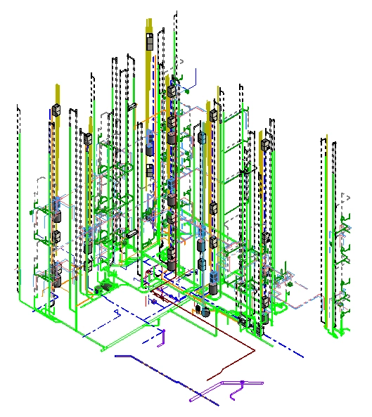
The plumbing model served as the central information source throughout the project. The modelling process focused on developing practical and coordinated routes rather than simply representing design intent.
Pipe elevations, service interfaces, congested areas, and available spatial clearances were reviewed as part of the coordination process.
COORDINATION PROCESS
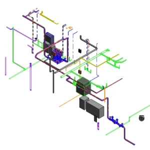
Typical coordination considerations included:
- Pipework versus structural elements
- Pipework versus other MEP services
- Limited ceiling and shaft spaces
- Pipe elevations and routing
- Wall and slab penetrations
- Accessibility and clearance requirements
- Drawing and model consistency
This created a reliable information chain in which the coordinated plumbing model became the foundation for sleeve placement and shop drawing production.
SLEEVE PLACEMENT
Accurate sleeve information was developed directly from the coordinated plumbing geometry.
The process included:
- Identifying required penetrations through walls, slabs, and other building elements.
- Reviewing pipe size, location, and surrounding construction conditions.
- Establishing sleeve locations within the BIM environment.
- Checking penetrations against structural and architectural constraints.
- Reviewing congested penetration zones for Constructability.
- Verifying sleeve locations against the latest coordinated pipe routes.
- Using the coordinated information to generate shop drawing views.
This model-based approach helped maintain alignment between the pipe location, penetration requirement, sleeve position, and construction documentation.
SHOP DRAWING PRODUCTION
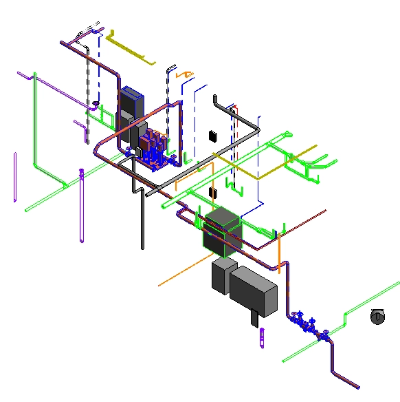
The coordinated BIM model was used as the basis for preparing construction-focused shop drawing information.
Deliverables Included:
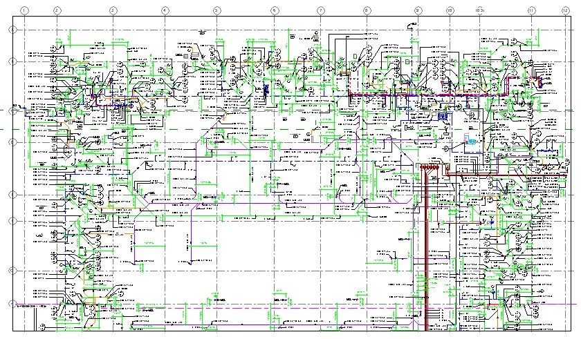
- Coordinated plumbing plans
- Sleeve placement drawings
- Relevant sections and enlarged views
- Setting-out dimensions
- Plumbing and sleeve annotations
- Reference information and tags
- Model-based construction documentation
The drawings were developed from the coordinated model to reduce discrepancies between 3D information and issued 2D documentation.
QA/QC & MODEL-TO-DRAWING CONTROL
Quality control was integrated into the delivery workflow rather than treated as a final standalone activity.
The team reviewed:
- Model-to-drawing consistency
- Sleeve positions against pipe routes
- Dimensions and annotations
- Drawing scale and view visibility
- Details and references
- Drawing revisions
- Alignment with the latest project information
- Final PDF/CAD or agreed project deliverables
INFORMATION FLOW
KEY PROJECT OUTCOMES
Plumbing BIM Modelling to Final Shop Drawings.
- End-to-end plumbing BIM delivery
- Coordinated plumbing routes developed in Revit
- Clash and spatial coordination reviewed in Navisworks
- Sleeve locations derived from coordinated pipe geometry
- Improved consistency between BIM models and shop drawings
- Coordination issues addressed before final documentation where applicable
- Structured construction information supporting site execution
- Model-based workflow connecting design coordination with fabrication and installation requirements
CHALLENGES & BIM-BASED RESPONSE
PROJECT IMPACT
The Nashville Project demonstrates how a coordinated BIM workflow can connect plumbing modelling, clash detection, penetration planning, and shop drawing production into one structured delivery process.
By using Revit as the central modelling environment and Navisworks for coordination review, the project established a consistent information flow from model development through construction documentation.
KEY TAKEAWAY
A coordinated BIM model can become the single source of truth—from plumbing routing and clash resolution to sleeve placement and shop drawings—helping deliver construction-ready information with greater consistency.