
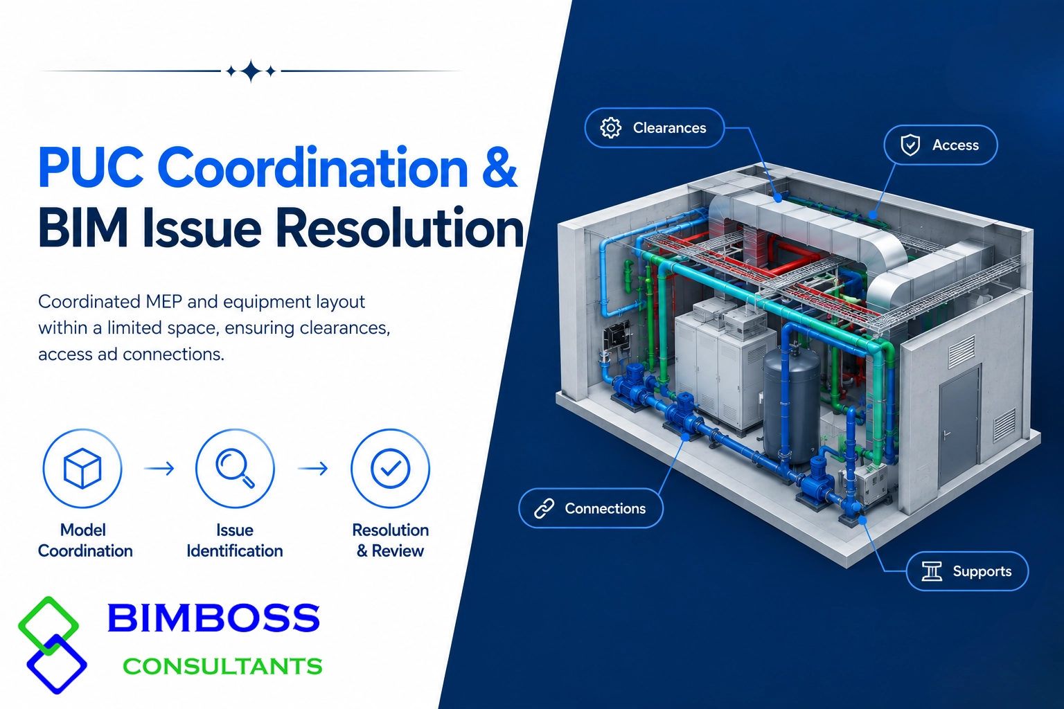
COORDINATING COMPLEX EQUIPMENT WITHIN A HIGHLY CONSTRAINED SPACE
PROJECT OVERVIEW
For this PUC coordination project, multiple mechanical and equipment components had to be accurately arranged within a limited enclosure while maintaining equipment clearances, service access, connections, cut-outs, supports and client requirements.
The objective was not simply to create a visually complete Revit model. The focus was to develop a coordinated and review-ready BIM representation that could support issue identification, resolution and downstream coordination.
THE CHALLENGE
The PUC arrangement involved several components competing for a highly restricted internal space. Fixed height and depth limitations reduced flexibility, while changes to one component could directly affect surrounding equipment and interfaces.
Key Coordination Challenges
- Limited cabinet or enclosure space
- Multiple equipment components sharing the same available volume
- Restricted height and depth
- Equipment and service clearance requirements
- Baseframe and support dependencies
- Connection and cut-out alignment
- Coordination between Inventor and Revit geometry
- Multiple PUC configurations requiring controlled variation
- Client markups affecting previously coordinated geometry
These constraints meant that every modelling change had to be evaluated against the surrounding arrangement.
OUR APPROACH
BIM coordination was carried out through a structured workflow designed to control changes and minimize secondary coordination issues.
01 — Information Review
Available drawings, equipment information, dimensions, markups and previous model information were reviewed before modelling began.
02 — Space Assessment
The fixed cabinet dimensions were established and the usable internal space was assessed.
03 — Equipment Placement
Major equipment was positioned first, followed by secondary components, connections and interfaces.
04 — Parametric Family Setup
Controlled parameters and family constraints were used to manage dimensions and configuration changes across PUC variants.
05 — Interface Coordination
Connections, openings, cut-outs, supports and adjacent components were coordinated with the equipment arrangement.
06 — 3D Model Review
The completed arrangement was reviewed through 3D views, plans and sections to identify potential issues.
07 — Issue Identification
Conflicts, clearance problems, geometry mismatches and constructability concerns were documented for resolution.
08 — Issue Resolution
Agreed changes were incorporated into the relevant Revit families and model geometry, followed by a recheck of affected interfaces.
09 — QA/QC
The model and supporting outputs were reviewed before issue.
10 — Coordinated Delivery
The final coordinated Revit model and required supporting outputs were prepared for downstream coordination.
CRITICAL COORDINATION ISSUES
Restricted Equipment Space
Multiple internal components were competing for limited cabinet volume.
Resolution: The equipment arrangement was reassessed and component positions were coordinated while retaining the required interfaces.
Buffer Vessel / WSHP Clearance
Equipment height and available internal clearance created an arrangement constraint.
Resolution: Equipment dimensions were reviewed against the available space before finalizing the PUC arrangement.
MVHR Interface
Connection and clearance requirements affected the surrounding cabinet geometry.
Resolution: The latest coordinated markup was incorporated and the revised interface was checked.
Baseframe Dependency
Final equipment placement depended on establishing the correct baseframe arrangement.
Resolution: The baseframe requirement was established before final Revit coordination and used as a placement reference.
Cut-Out Coordination
Required openings needed to align with the final equipment and connection locations.
Resolution: Cut-out positions were reviewed against the coordinated geometry and updated where required.
Inventor–Revit Coordination
Fabrication-oriented Inventor geometry and its Revit representation needed to remain consistent.
Resolution: Appropriate source geometry was reviewed and the Revit representation was coordinated against the latest available information.
PARAMETRIC REVIT FAMILY STRATEGY
Because multiple PUC configurations were required, a controlled parametric approach was used to reduce unnecessary remodeling and maintain consistency.
Key Family Setup Considerations
- Reference planes for key cabinet and equipment boundaries
- Constrained critical geometry
- Dimensional parameters for controlled width, height and depth changes
- Visibility parameters for optional components
- Nested components for repeated or independently controlled elements
- Consistent naming and parameter conventions
- Family flex testing before project implementation
- Rechecking connectors, cut-outs and interfaces after parameter changes
This approach helped manage configuration variations without rebuilding the entire family workflow for each PUC type.
QA/QC & COORDINATION REVIEW
Before final issue, the coordinated model was checked for the following:
Model Review Checklist
- Overall PUC dimensions
- Equipment positioning within enclosure limits
- Unintended geometry overlaps
- Equipment and service clearances
- Connection alignment
- Cut-out and opening coordination
- Baseframe and support arrangement
- Inventor and Revit geometry consistency
- PUC configuration and naming
- Views, sections and schedules
- Client comments and markups
- Final model revision and naming requirements
KEY OUTCOMES
The coordination process resulted in a controlled PUC BIM model despite significant spatial constraints.
Project Achievements
- A coordinated PUC model within the restricted available space
- Identification and resolution of coordination issues before delivery
- Reduced unnecessary rework through parametric family principles
- Managed Inventor–Revit coordination within the wider workflow
- A clearer model basis for downstream coordination and review
Potential coordination problems were addressed through a structured review process rather than isolated geometry changes.
FINAL TAKEAWAY
This PUC coordination project demonstrates how BIM modelling, parametric Revit families, spatial coordination and structured issue resolution can work together in highly constrained equipment environments.
The value of the BIM model was not simply its visual completeness. It provided a controlled representation that could be reviewed, challenged, updated and coordinated as the project progressed.